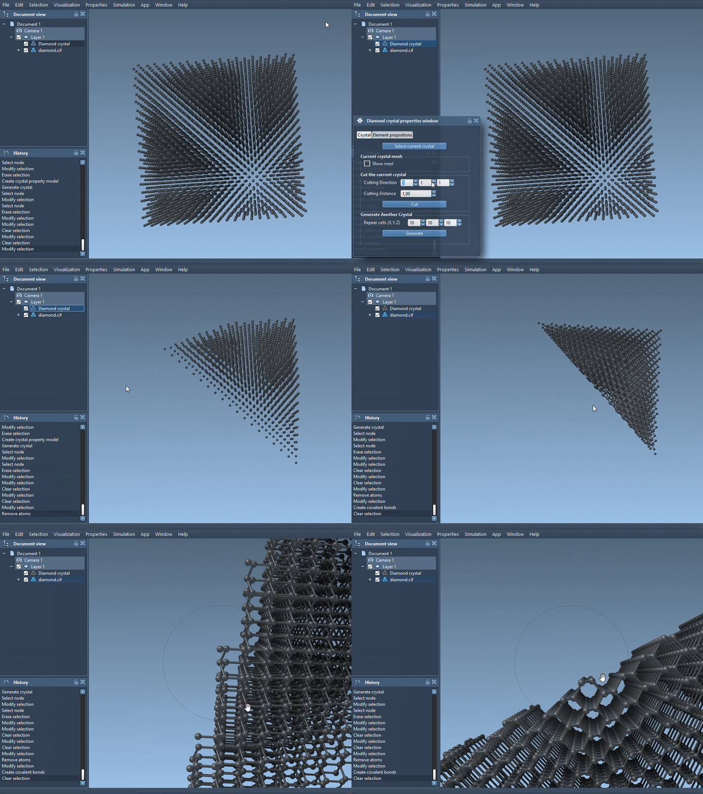
Crystalline materials in the real world often deviate from their ideal structures. Imperfections such as vacancies, substitutions, or interstitials—collectively known as defects—can dramatically influence material properties like conductivity, strength, and optical behavior. Simulating these defects realistically is essential for researchers and engineers designing materials with specific properties.
If you’ve worked with molecular modeling software before, you’ve probably run into limitations when trying to represent defects in crystals. Fortunately, the Crystal Creator Extension in SAMSON offers a straightforward way to add, visualize, and analyze defects inside crystal structures, with live visualization support.
Why model defects?
Perfect crystals are beautiful, but they’re not always realistic. Natural and synthetic materials almost always contain defects. Understanding how structures behave under these conditions is critical for:
- Designing durable semiconductors
- Predicting mechanical properties
- Studying catalysis at defect sites
- Simulating optical changes in doped materials
Defects in Diamond: A Practical Walkthrough
Let’s walk step-by-step through adding and analyzing defects in a diamond crystal using SAMSON and the Crystal Creator Extension.
1. Load the Perfect Diamond Structure
Start by importing a diamond CIF file using the Crystal Creator App. Several repositories like the RRUFF Project offer downloadable .cif files. When prompted, choose how many unit cells to generate and whether to include the mesh or symmetry operations.
2. Visualize and Minimize the Structure
Once loaded, use SAMSON to create bonds between atoms and apply a minimization protocol with the Brenner interaction model. This sets up a stable base structure before introducing any defects.
3. Introduce Occupancy-Based Defects
To simulate defects, open your CIF file in a text editor. Locate the section at the end that looks like this:
|
1 2 3 4 5 6 |
loop_ _atom_site_label _atom_site_fract_x _atom_site_fract_y _atom_site_fract_z C 0.00000 0.00000 0.00000 |
Replace it with the following, adding the _atom_site_occupancy line:
|
1 2 3 4 5 6 7 |
loop_ _atom_site_label _atom_site_fract_x _atom_site_fract_y _atom_site_fract_z _atom_site_occupancy C 0.00000 0.00000 0.00000 0.95 |
The occupancy value (0.95) means each carbon atom has a 95% chance of being present at that position. You can assign different probabilities to simulate various defect concentrations.
4. Load and Compare
Load the modified crystal file back into SAMSON. After bond generation, compare this defected model to the original minimized structure. You should observe changes in local coordination, symmetry, or even microstructural features—valuable insights for understanding defect behavior.
5. Iterate
Try increasing or decreasing the occupancy value, or introduce different defect types by substituting atom labels. Combine this feature with the ability to cut crystals in specific directions (e.g., [111]) to simulate surfaces and expose defect planes.

Conclusion
This workflow provides both a simple and flexible method to incorporate realistic defect models in your crystal simulations. Whether you’re studying catalytic activity or material strength, introducing electronic, structural, or chemical variability can improve the relevance of your models.
Learn more and explore other crystal generation features in the official SAMSON documentation: https://documentation.samson-connect.net/tutorials/crystal-creator/generating-crystal-models/.
SAMSON and all SAMSON Extensions are free for non-commercial use. Download SAMSON at https://www.samson-connect.net.


