



A crystal model can look complete and still be difficult to use: the full periodic structure may hide the surface or orientation you want to inspect. If your goal is to study a particular crystal cut, you do not necessarily need to build a new model from scratch. You can import a CIF file into SAMSON, inspect its properties, and use Crystal Creator to cut the structure along a chosen direction.
This workflow is useful when you want to move from a crystallographic structure to a model that is easier to examine. It also keeps an important distinction in view: a CIF can describe unit-cell data as well as symmetries, defects, and substitutions, so the imported model may contain more than a simple, idealized arrangement.
Start with a CIF structure
Install the Crystal Creator Extension if it is not already available. You can find CIF files through sources such as the American Mineralogist Crystal Structure Database or the RRUFF Project Database. Open a CIF file in SAMSON. The import window lets you choose the number of unit cells and whether to import the data without symmetries or display the mesh. After you click Open, the crystal structure and its property model appear in the data graph.
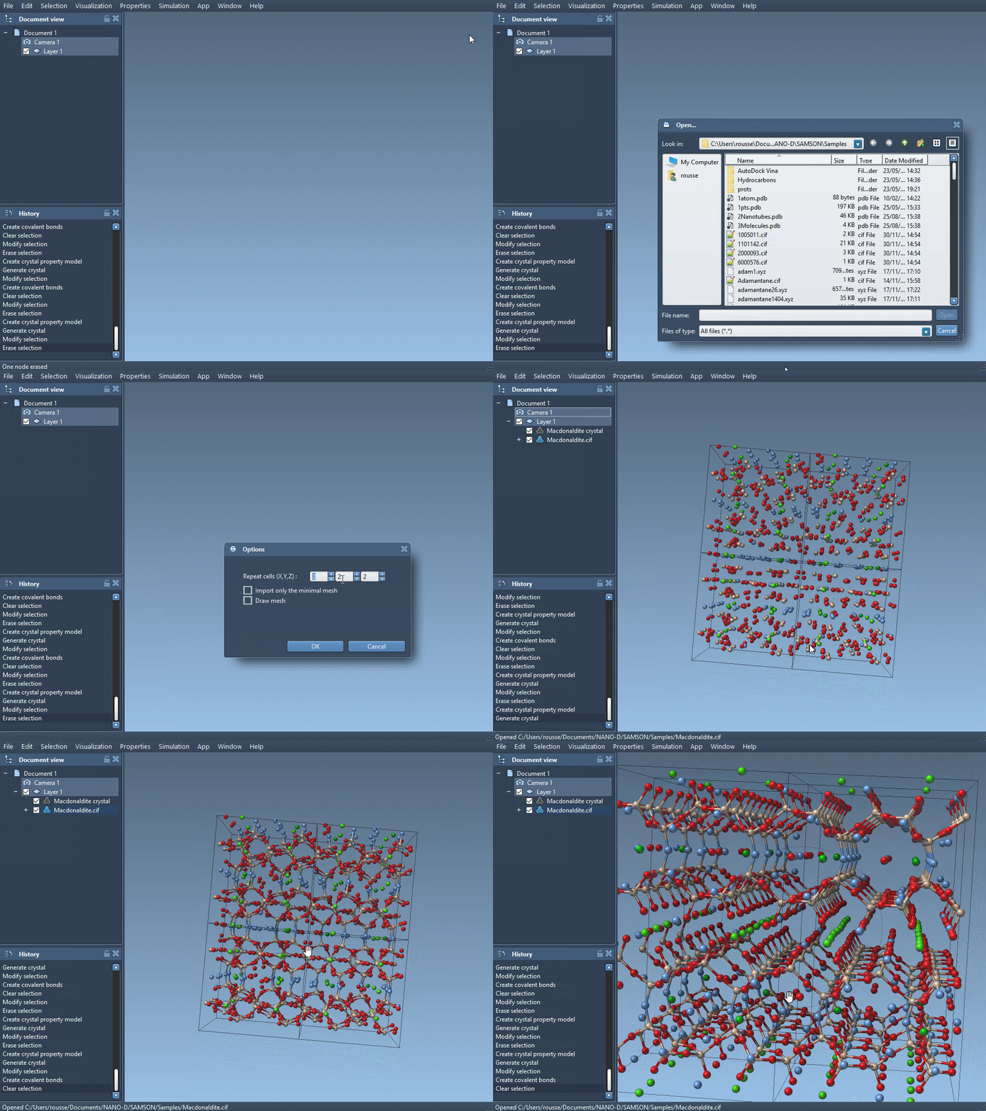
Different CIF files can produce structures with different unit-cell contents. Some files describe defects or substitutions, and Crystal Creator uses those descriptions when generating the crystal. That matters when you are interpreting what you see: the model may reflect the supplied crystallographic data rather than a perfectly repeated ideal structure.
Find the cutting controls
To access the crystal’s controls, right-click its property model and choose properties. In the first tab, you will find tools to locate the crystal, show its mesh, cut it, or generate another crystal. The cutting controls use four boxes: the first three specify the cutting direction as Miller indices, and the fourth specifies the distance from position 0 where the cut is made.
In practice, this means you need to think about both the orientation of the cut and where it should pass through the model. Changing the direction changes which crystal plane you are examining; changing the fourth value moves the cut relative to the crystal’s reference position. If a first cut is not where you expected, check both parts of the input rather than changing the direction alone.
Try the [111] diamond cut
A useful example from the tutorial is a diamond crystal cut in the [111] direction. Open a diamond CIF, select the property model, and enter 111 as the cutting direction using the three Miller-index boxes. Then set the cut position with the fourth box and inspect the result. This cut reveals diamond’s compact hexagonal structure.
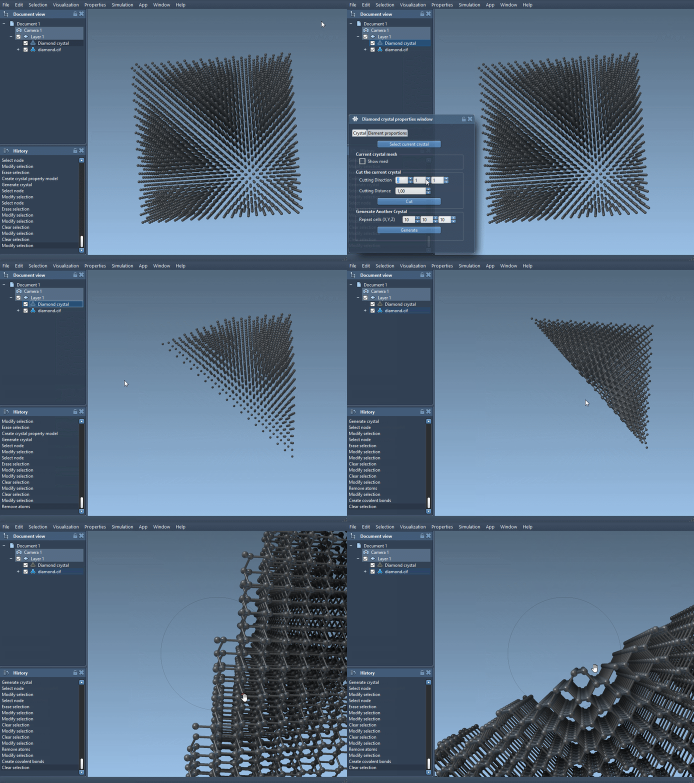
This example is a practical starting point, not a requirement to use the same crystal or direction. You can import another CIF and explore its structure in the same way. The mesh checkbox can help you view the crystal mesh, while the crystal-location button can help you find the model in the scene when you need to orient or inspect it.
Check the model when composition matters
If the crystal includes defects or substitutions, use the second tab of the property window to check whether their proportions have been respected. Select check atoms ratio to see, for each atom site, whether its presence or absence ratio matches the data. This is especially useful before drawing conclusions from a model whose composition is not uniform.
The main takeaway: begin with a CIF that represents the structure you need, then treat the Miller indices and cut position as separate choices. That simple habit makes it easier to explore crystal surfaces without confusing the orientation of a cut with its location.
For the full workflow, examples, and instructions for creating custom crystals, see the Crystal Creator documentation.
Note: SAMSON and all SAMSON Extensions are free for non-commercial use. Get SAMSON.