



A crystal model can look plausible and still be difficult to trust. The unit cell may be entered with the wrong coordinate convention, a cut may not expose the structure you expected, or partial atom occupancy in a CIF may be overlooked. These problems are easier to address when you treat crystal building as a sequence of checks—not just a way to make a structure appear on screen.
This workflow focuses on a common modeling task: importing a crystal or building one from unit-cell data, then checking that the resulting model reflects the information you intended to use.
Start with a source structure—or a clear unit cell
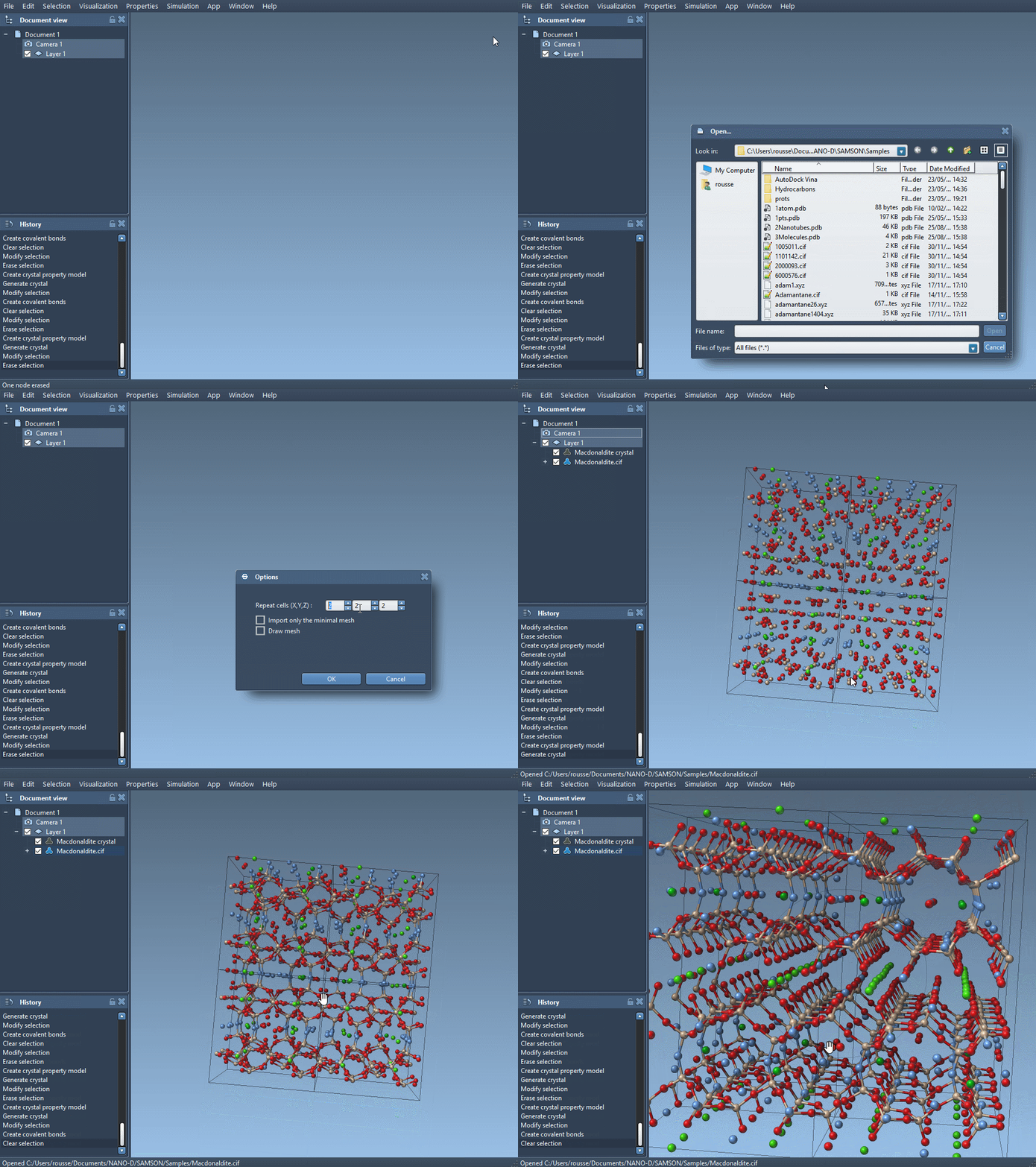
If you have a CIF file, open it in SAMSON with the Crystal Creator extension. During import, choose how many unit cells to generate and whether to include symmetry or display the mesh. The choice depends on what you need to inspect: a larger periodic model can help show the repeated structure, while importing data without symmetries may suit a different inspection workflow.
Crystal files can also describe defects or substitutions. The generated crystal can therefore contain variation rather than identical copies of every site. That is not necessarily a modeling error: occupancy information in the CIF can describe the probability that a site is present.
When building from scratch, keep coordinates and cell data consistent
In Crystal Creator, you can define the unit cell using its cell parameters or its vectors. The Write Matrix/Write Vectors control lets you switch between those notations. You also specify the position of the crystal origin, the number of unit cells to generate, and the atoms in the unit cell.
Before entering atom positions, check which coordinate convention is active. In the relative-position tab, coordinates describe proportions of the unit-cell vectors. In the absolute-position tab, they are distances in angstroms. The same numbers mean different things in those two modes, so matching the coordinate values to the selected tab is essential.
For example, a face-centered cubic aluminum unit cell with a lattice parameter of 4.05 Å can be represented in relative coordinates by:
|
1 2 3 4 |
Al 0 0 0 Al 0 0.5 0.5 Al 0.5 0 0.5 Al 0.5 0.5 0 |
This is a compact description of the contents of one unit cell; the requested number of cells determines how far the model is repeated. For a diamond structure, the tutorial gives a cubic cell with a lattice parameter of 3.60 Å and eight carbon positions. Labels such as C0 and C1 identify entries while retaining the element symbol at the start of each label.
Use a cut as a structural check
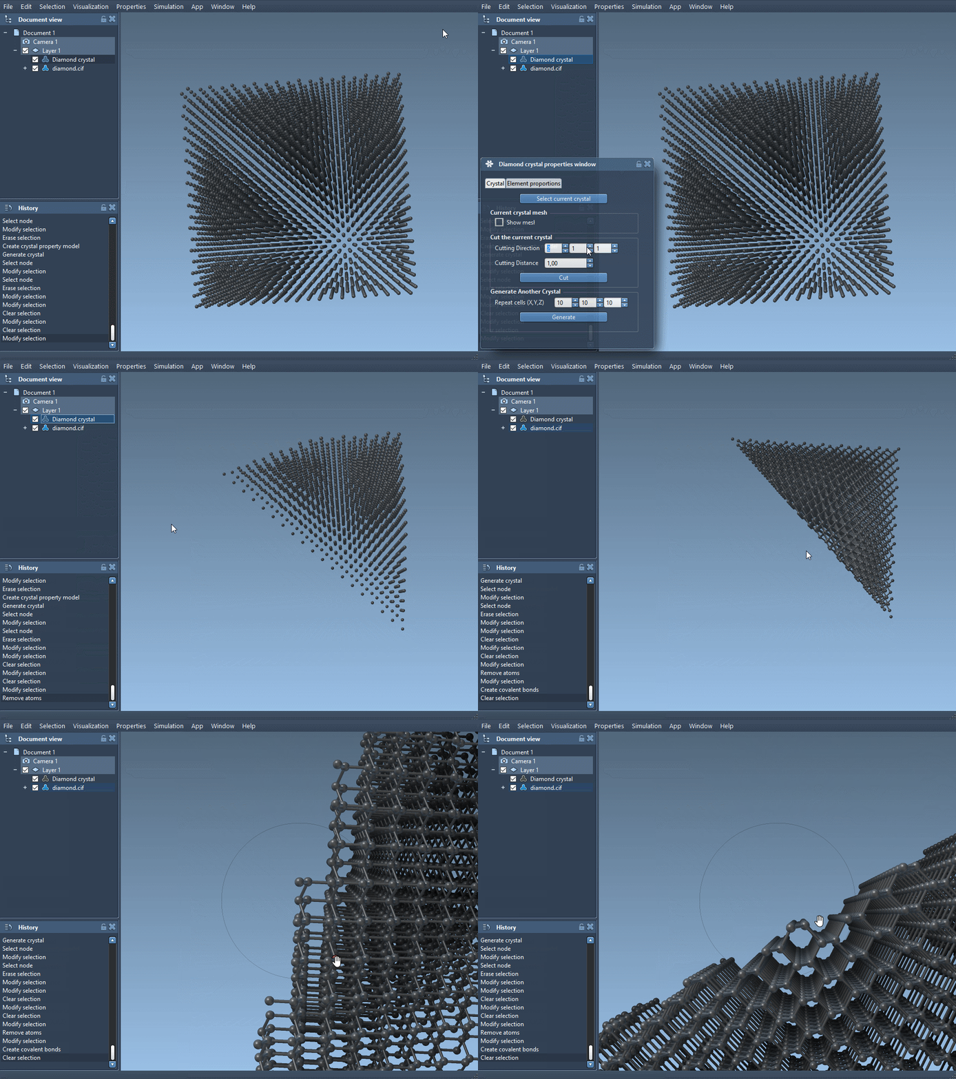
Once a crystal has been generated, open the property model’s properties to find the crystal, show its mesh, cut it, or generate another crystal. The cutting controls use three Miller indices for the direction and a fourth value for the cut’s distance from position 0. A useful test is to load a diamond crystal and cut along [111]; the resulting view shows its compact hexagonal arrangement.
A cut is more than a presentation choice: it gives you another way to inspect whether the generated structure has the orientation and arrangement you meant to examine. If you are working from a CIF with partial occupancy, the second properties tab can also check the atom-site ratios. Use check atoms ratio to see whether the presence or absence of atoms at each site respects the specified ratios.
A short, repeatable checklist
- Confirm the unit-cell dimensions or vectors before generating the crystal.
- Check whether your atom coordinates are relative or absolute.
- Choose the number of unit cells needed for the inspection at hand.
- For CIF imports, consider whether symmetry and mesh display should be enabled.
- If the CIF contains defects or substitutions, inspect the site ratios rather than assuming every site is fully occupied.
- Try a cut in a known direction, such as
[111]for the diamond example, to examine the structure from another perspective.
Crystal models are easier to interpret when their cell definition, coordinates, and occupancy information are checked together. You can save crystal settings from the property window and reuse them later, which is helpful when you want to return to a particular model setup.
For the complete walkthrough and additional examples, see the Crystal Creator documentation.
Note: SAMSON and all SAMSON Extensions are free for non-commercial use. Get SAMSON.